“…The live demonstration provided a stage for the best performing team of each category to showcase their winning aircraft” – Singapore Amazing Flying Machine Competition
After a couple of weeks since the end of the Singapore Amazing Flying Machine Competition, I finally have the chance to sit down and reflect on the past 5 months of hard work.
A big challenge lies ahead…
When I first received the challenge booklet for Category D1 – Semi-autonomous from my project supervisor, Mr Albert Sng, I was taken aback by the changes made to the competition. This being the SAFMC’s 10th year anniversary, it bore no similarity to any of the past years’ tasks. The previous years’ tasks were of an obstacle course nature, including the signature task.
In 2016, the signature task was to drop a payload (golf ball) into a target area, and in 2017, the signature task was to collect a chemical sample from a tray. This year, some of the tasks we had to clear include:
- Identifying, and attempting to rescue casualties in the arena,
- Transporting of rescue personnel from headquarters to a forward operating base (FOB),
- Building a blockade using the provided rectangular blocks,
- And lastly, the hardest task of all; To collect, and deliver freshwater from a lake to the FOB.
You can read up more about the tasks in the challenge booklet for Category D1 here:
https://safmc.com.sg/wp-content/uploads/2018/02/SAFMC-2018-CAT-D-CHALLENGE-BOOKLET-v1.1.pdf
Given the scale of the challenge provided, I knew that I had to come up with a different approach to complete my project within the limited time frame.
A change in focus; choosing the right parts
Traditionally, as participants, we are expected to develop a quadcopter platform that flies well before proceeding to add modifications which will allow the quad to complete the tasks given. But I know that if I adopted this approach, I would not be able to complete in time. Instead I directed my focus towards testing and development of ideas to clear the tasks.
For the quadcopter I decided to go with something that I’ve trusted; to use a Flight controller running Betaflight firmware, and pair it with ESCs running BLHeli firmware. A quick consultation with Total Rotor and I eventually settled for the iFlight Revo Bee32 F4 Pro Flight Controller, along with the iFlight iPeaka 35A 4-in-1 BLHeli_32 ESC.
With that sorted, I can finally get started with designing and testing new contraptions for clearing the tasks set by the SAFMC.
Frame design; from rendering to reality
After hours of research to find the perfect quadcopter frame, I noticed that none of what’s available in the market fit my requirements, and that it was better for me to design a frame completely from scratch. The process was not as straightforward as it meant that I had to pick up CAD drawing, something I have no experience in. Nonetheless, after a solid week of Autodesk Fusion 360 courses on Udemy and fumbling around with the software, I began to design my very own frame.
The first few design iterations for the frame had modular arms and two brace plates, inspired by the Armattan Rooster. However, it became apparent that the setup is too weak for the intended application, which involves lifting loads of up to 2kg. Hence the call was made for a unibody design instead.
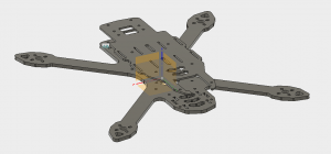
Partial CAD Assembly in Fusion 360
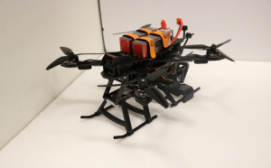
A month of prototyping later, and the final product was a frame that was truly unique. Some key features of the frame include 2 separate 30x30mm mounting holes for mounting the electronics, and a top plate that natively supports 2 LiPo batteries to be run in parallel for maximum flight time. There are cut-outs for mounting 2 XT60 PCBs at the rear of the frame for easy power connection as well.
Satisfied with the final design, it was time to convert the assembly into an actual physical product. Having no prior knowledge or experience about the process of CNC milling, I engaged the help of Jaymes Tan from Total Rotor to help bring my design to life. His knowledge helped me out a lot, and we used his in-house CNC milling machine to cut out the parts of my frame. The cutting process took an entire day, and I picked up many skills such as operating the CNC machine, and proper methods of finishing the cut carbon parts. Thankfully, the design tolerances were just right, and all the parts fit as they should.
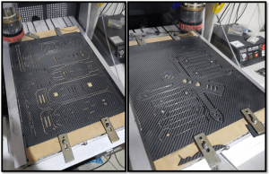
Milled Carbon Plates
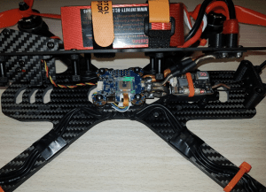
The build process followed soon after. For the electronics, I picked t iFlight Revo Bee32 F4 Pro Flight Controller with ICM20608, and paired it with the iFlight iPeaka 35A 4-in-1 BLHeli_32 ESC. The inclusion of the JST cable provides direct connection between the two boards, thus interfacing them was a breeze. This was by far the easiest build I’ve ever done, due to the simplicity of the iFlight stack, as well as the space inside the frame. This was also one of the cleanest builds I’ve ever done, thanks to the 3D printed accessories designed by Adam Garratt of Total Rotor. Due to the high quality of the iFlight electronics, the maiden flight took place without a hitch too.
The full parts list used for the quad build are as follows:
- Frame: Custom 300mm True X “Freestyle” Type
- Motors: T-Motor F40 Pro V1 2400kV
- ESCs: iFlight iPeaka 35A 4-in-1 BLHeli_32 ESCs
- Flight Controller: iFlight Revo Bee32 F4 Pro Flight Controller with ICM20608
- RX Receiver: FrSky R-XSR
- Camera: Runcam Eagle 2
- Video Transmitter: EWRF e708TM3 5.8G 48CH Adjustable Power FPV VTx with OSD Support
- FPV Antenna: Lumenier Axii
- 2x Matek Micro 5V/12V BEC for powering LEDs
- 4x WS2812B LEDs (8×1)
- 2x XT60 PCBs, connected in parallel.
The next step is to figure out a way to interface the aircraft with the various payload configurations that the team and I have developed for clearing the tasks.
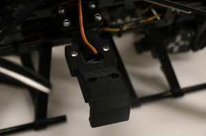
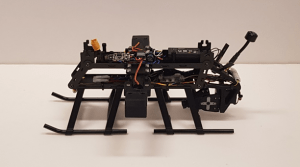
The initial idea involved using nylon strings suspending from different points of the frame to the payload configurations. This had a fundamental problem as the winds generated from the propellers spinning caused the payload to swing back and forth, significantly affecting the craft’s stability. The idea was scrapped in favour of a rigid mounting system. This system comprises of two main parts; two servoless retracts mounted on the aircraft, a 3D printed hook attached to each of the servoless retracts, and two square carbon rods attached to each of the payload configurations. The team and I also worked with Adam to further optimize the system with custom designed 3D printed landing skids, that has integrated guiders for the square rods. The landing skids also acts as a limiter so that the payload remains rigidly mounted while the aircraft is in flight, hence eliminating the stability issue brought about by the nylon strings. Adam had also helped design a two-axis servo gimbal camera system, which hangs off the back of the aircraft. This, along with the landing skids, allows the aircraft to land and attach its payload configuration of choice autonomously.
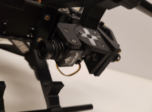
Runcam Eagle 2
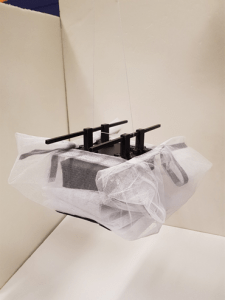
On the bench, the system proved to work a treat. No matter how hard we shook the test assembly, the payload did not detach. As a bonus, the landing skids held the square rods in place perfectly.
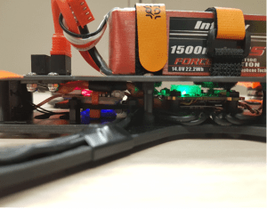
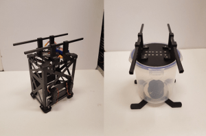
The final step to completing the aircraft is to figure out a way to house all the extra electronics needed for the competition, which is why one will notice that there are 4 extra rectangular cutouts on the aircraft’s main plate. They are slots for the modular subframe system, a carbon fibre assembly consisting of two separate levels of mounting plates for the electronics. The modular subframe system is also packed with clever features. As the name implies, the assembly is modular, and can be installed or removed from the aircraft via the 4 rectangular cutouts. The assembly also offers ease of maintenance thanks to its open hatch design. Lastly, the assembly can be powered through either an XT60 lead from the aircraft, or an external LiPo altogether.
Building the modular subframe was made simple thanks to the flexibility of the mounting plates, which can be re-designed to fit any needs. The designs can then be either cut with G10 fibreglass, or 3D printed. The open hatch design also allowed for an easier build process. In the end, it took a full day of work to get the modular subframe fully working, and the maiden flight of the aircraft in its entirety was successful as well. And with just a few days remaining, it was finally time to get some practice in.
Competition Day
Custom 300mm True X “Freestyle” Type
Competition day soon followed, and we were given a total of two attempts to complete the challenge. Given the amount of practice we had in total prior to challenge day, we were not expecting ourselves to do as well as the other competitors comprising of students from other polytechnics as well as universities. However, that was not the case, as we managed to emerge as one of the top performing teams for the competition. We were also the only team for the day that not only attempted the freshwater delivery, but also succeeded in doing so. During the presentation, the judges were impressed with the quality of work done, as well as the many innovations that the aircraft and its payload configurations had.
A few days later, we received a call from DSO to represent Category D1 for the live demonstration during the Awards Ceremony. The live demonstration provides a stage for the best performing team of each category to showcase their winning aircraft to the audience consisting of ministers, news journalists, fellow competitors as well as members of the public. For the demonstration, our team was to demonstrate the freshwater delivery task, as we remained to be the only team that is able to complete the task successfully. Shortly after our run, we were then interviewed by the Guest of Honor for the event, who showed keen interest in the work we’ve done for the competition. Having our hard work recognized and valued brought a huge sigh of relief, as it meant that all the long hours that we’ve put into this endeavour, including many long nights spent in the lab was well worth it. In the end, we emerged as champions for Category D1.
To conclude, we want to thank iFlight RC as well as Total Rotor for providing us with the electronics that allowed our aircraft to fly so superbly. We also want to thank Jaymes Tan of Total Rotor for helping us with both frame cutting and troubleshooting, as well as Adam Garratt for his expertise in SolidWorks 3D design. Last but not least, we want to thank Nanyang Polytechnic for providing us with the facilities in school such as our adequately equipped lab, 3D printer and CNC milling machine, and also helping us with procuring our project components. Without their help, this endeavour wouldn’t have been this successful.